Why Local Tweaks Vanish Across Iterations
When a mechanical component fails during field testing, engineers often add local reinforcements directly in the slicer—such as increasing wall counts around a hinge pin or using solid infill under a bolt flange. When the CAD file receives its next revision, loading the updated model frequently drops those part-level overrides, causing an unexpected failure in the newly printed batch.
Critical Failure Points in Revision Slicing
- Internal ID Remapping: Slicers link modifier modifiers to specific mesh sub-object indices; altering CAD solid counts shuffles these indices and disassociates applied exceptions.
- Plate-Level Drag-and-Drop: Dragging a revised STEP file directly onto the build plate creates a fresh object instead of updating the existing tree entity, discarding all previous sub-part rules.
- Invisible Reversion to Baseline: A forgotten exception produces no compiler warning or slicing error; the slicer smoothly computes standard global parameters without flagging missing overrides.
- Project State Desynchronization: Engineering teams distributing standalone STL/STEP revisions without accompanying 3MF project packages force print technicians to re-guess intended local scopes.
Systematic Prevention of Regression Failures
Maintaining parametric integrity requires disciplined file handling techniques, coordinate anchoring, and intentional verification before sending toolpaths to machines.
When you assign an override in Bambu Studio, OrcaSlicer, or PrusaSlicer, the software tags that parameter set to a specific sub-mesh pointer inside the project tree. This pointer depends on stable hierarchy ordering within the assembly file.
Exporting an updated model with added or removed sub-features breaks that indexing chain. The slicer cannot determine which new boundary volume matches the previous exception, dropping the parameter assignment and falling back to the global baseline profile.
- Sub-mesh entity names in multi-body STEP files shift when features are reordered in the CAD tree.
- Custom cylinder or box modifier volumes remain stationed at obsolete XYZ world coordinates.
- Material and perimeter overrides silently reset to plate default values during full object replacements.
Deleting the old part on the virtual plate and dragging the new revision into the viewport instantly wipes every custom setting. Instead, use the native Reload command by right-clicking the parent object in the tree view and pointing the slicer to the newly exported file.
This command instructs the slicing engine to swap out underlying polygon data while keeping existing modifier volumes, plate coordinates, and custom process overrides intact wherever spatial overlap permits.
- Right-click the object node and execute Reload from Disk rather than deleting and re-importing.
- Keep the CAD origin point locked across all revision releases to prevent geometric displacement.
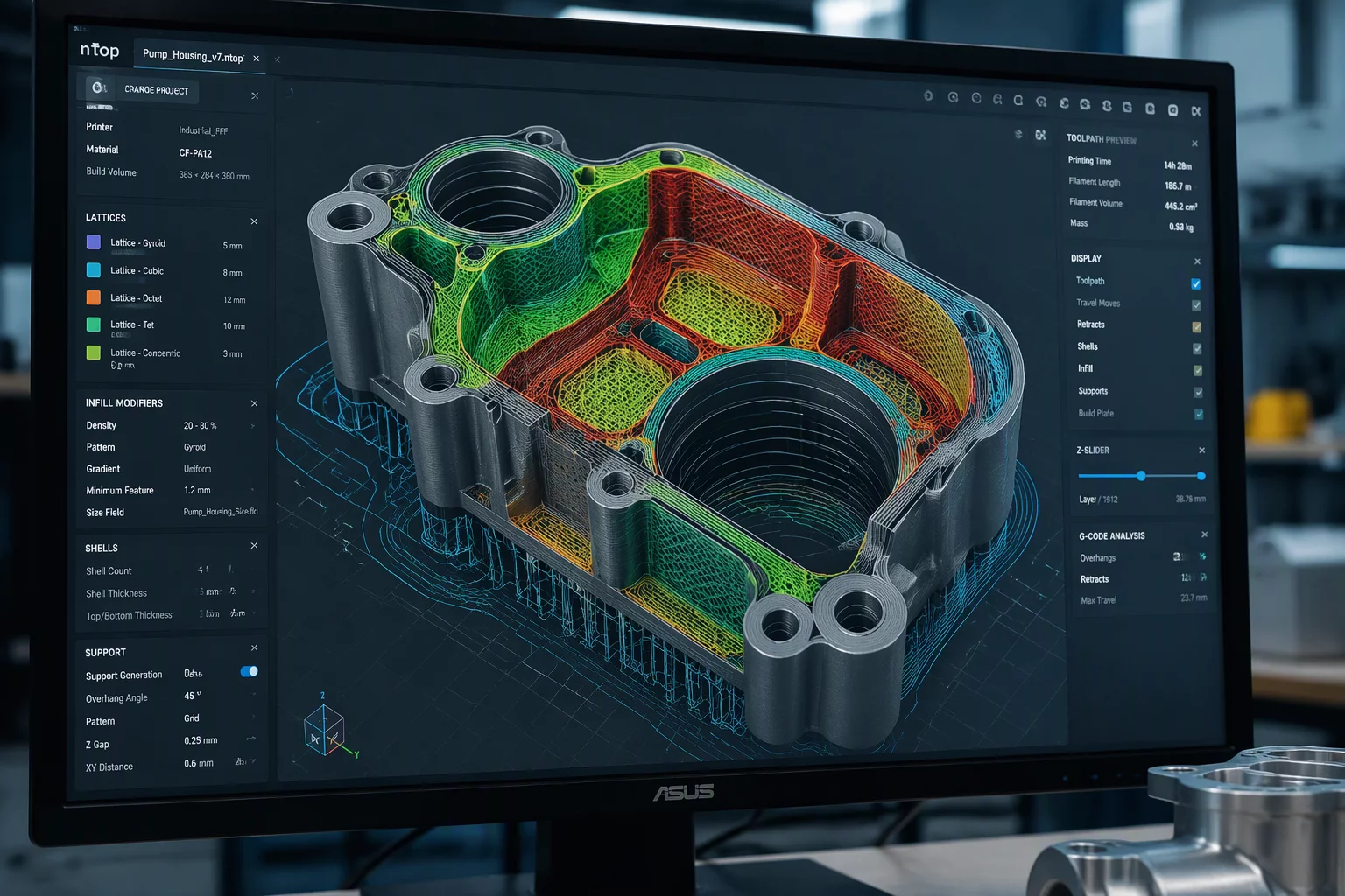
Visual previews can be deceptive when inspecting complex geometry. An engineer must never trust uniform top-surface colors; you must cycle the preview visualization mode to Line Type or Speed to inspect structural infill patterns directly.
Drag the vertical layer slider to the exact plane where local reinforcement was mandated. If the high-density concentric pattern reverted to standard sparse grid infill, the exception was dropped during reload and must be reapplied.
- Inspect cross-sections in Line Type view to confirm wall loops match reinforcement expectations.
- Examine the object tree hierarchy on the left panel to ensure each sub-part maintains its override icon.
Engineering teams prevent forgotten exceptions by treating slicer project files as first-class version-controlled code. Never hand off raw geometry files to machine operators without a documented 3MF container that captures every part-level exception.
Record notes directly inside the slicer project metadata detailing which sub-volumes require specific mechanical rules, ensuring any team member handling the next iteration can audit the tree before launching a production run.
- Store project 3MF files alongside CAD revisions in central repository branches.
- Document every part-level override in project notes with exact layer ranges and density values.