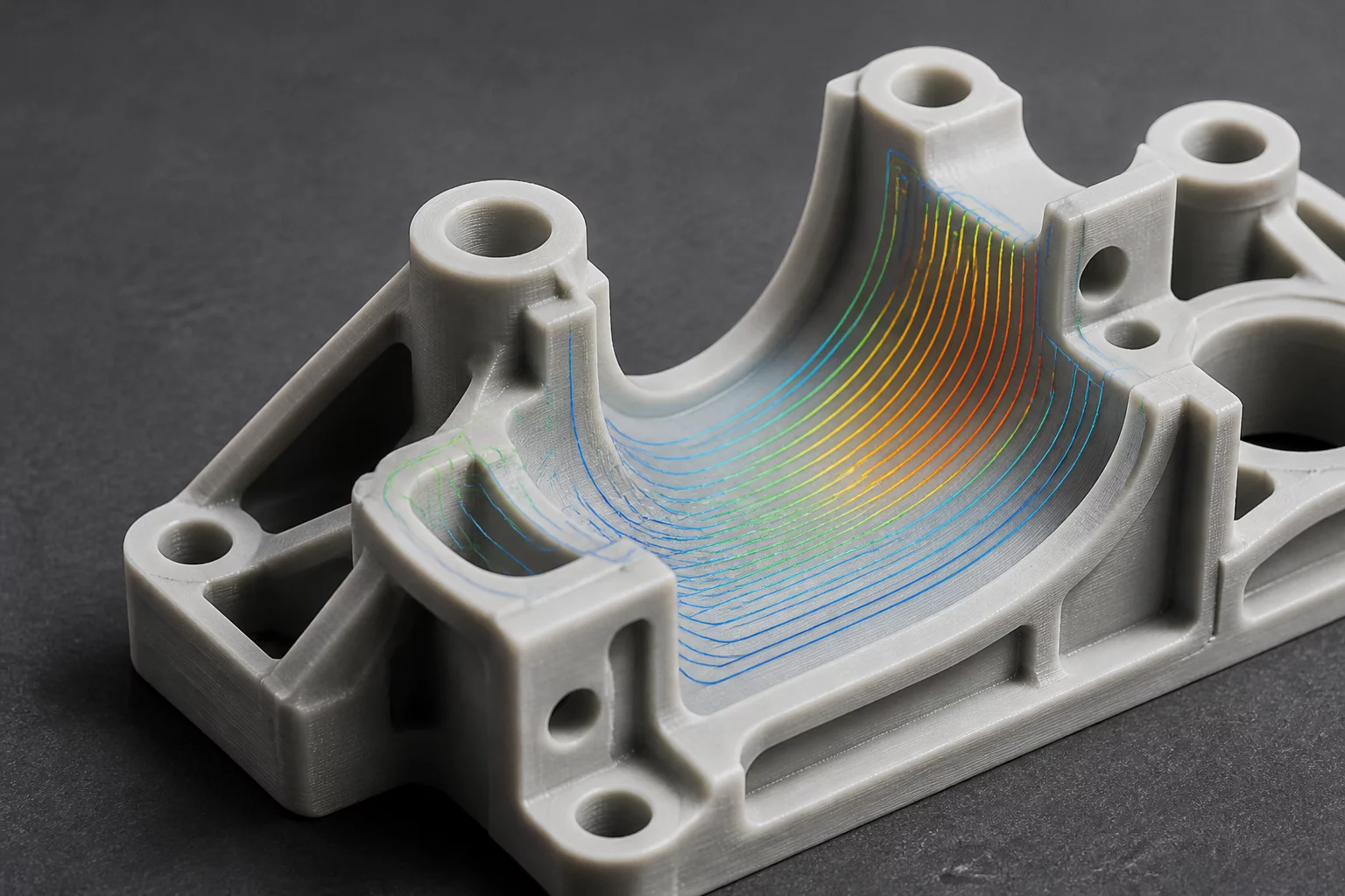
ISOLATING SECONDARY EFFECTS IN SLICER OVERRIDES
Applying a modifier volume or part-level override to correct localized bridge sagging or wall deflection frequently introduces unpredicted defects at the transition boundary. Modern slicing algorithms recalculate toolpath segments globally within each layer slice, causing subtle alterations in extrusion speed, pressure advance equilibrium, and cooling dwell times that propagate outward into otherwise pristine regions of the print.
Core Parameter Propagation Realities
- Extrusion Width Boundary Step: Increasing wall loops or local line width abruptly from 0.42 mm to 0.60 mm forces instantaneous nozzle pressure changes, producing surface bulges at modifier intersection planes.
- Z-Seam Relocation Dynamics: Altering perimeter geometry inside a local volume shifts the path planner cost calculation, pushing the aligned seam onto highly visible exterior cosmetic faces.
- Layer Dwell Time Disparities: Slowing down speed across an overhang zone raises total layer time, unexpectedly altering the cooling gradient and surface gloss of untouched peripheral features.
- Infill Anchor Rupture: Switching infill density inside a modifier mesh creates virtual internal boundary walls that sever continuous raster lines and reduce overall shear resistance.
RESOLVING CASCADE DEFECTS METHODICALLY
When a local fix destabilizes toolpaths elsewhere on the component, follow a systematic audit sequence to isolate parameter scope and eliminate secondary defects without sacrificing the primary mechanical correction.
Engineers routinely add a localized cylinder modifier around bolt holes to boost wall loops from three to six, aiming to resist thread-tapping torque without lengthening total cycle time across the entire plate. However, this sudden transition abruptly changes nozzle acceleration and internal perimeter count at the modifier boundary.
The slicer terminates the extra inner loops directly against standard walls, causing localized over-extrusion and noticeable banding on external surfaces. Inspect the toolpath preview at 100% zoom to verify how the engine caps perimeter ends.
- Extend the modifier mesh at least 3 mm past the bolt boss to let decelerations dissipate within non-critical structural mass.
- Adjust inner wall overlap percentage to prevent volumetric accumulation where extra loops meet the baseline envelope.
- Enable precise wall generation mode to standardize toolpath segment spacing across the transition volume.
Reducing travel velocity to 20 mm/s through a local modifier successfully prevents droop on steep chamfers. Simultaneously, the extended hotend contact time heats the polymer longer, producing a glossy horizontal stripe across surrounding matte semi-crystalline surfaces.
The visual flaw occurs because polymer crystallinity and surface reflectivity correlate tightly with cooling duration and extrusion temperature. Addressing this requires harmonizing cooling fan thresholds rather than simply slowing travel speeds in isolation.
- Increase auxiliary part cooling fan output specifically for layers housing the modifier rather than dropping baseline feed rates excessively.
- Maintain consistent outer perimeter speeds across the entire layer while applying reduced speeds exclusively to inner unsupported loops.
Switching from 15% gyroid infill to 50% grid infill inside a local load-bearing zone creates an artificial internal interface. Instead of blending the toolpaths, modern slicers slice the modifier as an enclosed volume and add internal perimeter shells around its contour.
These internal vertical shells break continuous infill continuity, generating an internal shear plane where layers crack under lateral torsional loads. Mitigating this issue requires modifying infill generation parameters.
- Set internal perimeter count to zero within the modifier sub-tree so infill lines anchor directly into adjacent cells without synthetic partition shells.
- Employ gradient infill patterns or adaptive cubic geometry instead of hard-edged block modifiers when reinforcing structural intersections.
When custom modifiers alter wall start angles or add short retractions near an internal rib, the slicer path optimizer often shifts the outer Z-seam from a concealed rear corner to an exposed curved fillet. The operator fixes an overhang but inadvertently degrades cosmetic exterior quality.
Automated seam algorithms weigh travel time, sharp corners, and start points across each calculated loop. Modifying travel sequences within one quadrant frequently tilts the solver cost equation across the entire layer.
- Apply explicit manual seam painting on exterior contours before testing localized modifier parameters.
- Lock seam position to back or custom coordinates in global parameters so localized sub-settings cannot trigger unexpected seam relocations.