Establishing The Three-Tier Inheritance Model
Production build plates routinely combine heavy mechanical fittings with cosmetic panels and flexible seals. Applying toolpath parameters universally forces sub-optimal compromises between tensile rigidity and print speed. Reliable slicing requires strict demarcation across global profiles, per-object configurations, and localized modifier volumes.
Foundational Scope Principles
- Global Scope Baseline: Enforces universal machine kinematics, baseline thermal envelopes, bed adhesion primitives, and default layer height increments across the complete print space.
- Object-Level Isolation: Overrides shell counts, infill geometry, support generation, and seam placement for individual discrete models without corrupting neighboring geometries.
- Part & Modifier Demarcation: Applies targeted density increases, interface layer adjustments, or alternate perimeters strictly inside bounded geometric coordinates or CAD split bodies.
- Revision Resilience: Confining local exceptions to designated sub-volumes prevents global preset upgrades from unintentionally breaking calibrated structural tolerances.
Analyzing Each Hierarchical Layer
Slicers evaluate toolpaths through sequential inheritance trees. Parameter conflicts and printing defects almost invariably emerge when an engineer applies an intervention at an inappropriate structural level.
The global tier represents the environmental baseline for the entire build plate. It determines foundational variables including extruder temperature curves, heatbed thermal equilibrium, linear advance values, and base extrusion multipliers. Because these parameters correspond directly to hardware constraints and raw polymer rheology, modifying them downstream introduces unpredictable physical behaviors.
Global settings serve as the single source of truth for the project. When multiple objects print alongside one another, global cooling fan thresholds and volumetric speed ceilings prevent thermal runaway and nozzle clogs across all toolpaths.
- Establishes consistent chamber heating, bed thermal targets, and maximum flow rate ceilings.
- Regulates global acceleration boundaries, non-print travel velocity, and z-hop behavior.
- Provides a clean standardized template whenever new CAD geometry enters an existing job setup.
When distinct mechanical assemblies share a common build plate, global uniformity becomes inefficient. A structural mounting bracket requires six perimeter walls and dense gyroid infill, whereas an adjacent cosmetic clip needs only two perimeters and high-speed sparse infill to conserve cycle duration. Object-level overrides satisfy these divergent criteria.
In modern slicing engines, right-clicking a model allows operators to assign dedicated layer heights, seam placement rules, and support mechanics. These parameters supersede global presets exclusively for that selected geometry while leaving unaffected properties linked to the main process profile.
- Permits mixing rigid structural cores with delicate cosmetic shells in a unified print operation.
- Applies support generation exclusively to geometries with severe overhangs without triggering supports on adjacent parts.
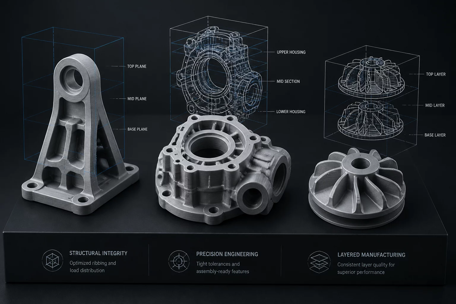
The third tier introduces sub-part precision within the boundary of an individual component. By incorporating modifier shapes, height range modifiers, or multipart assembly bodies, engineers designate volumetric zones where parameters deviate from both object and global norms.
This approach solves localized stress challenges. Instead of reinforcing an entire 500-gram component to withstand shear loads around a single bolt hole, a compact cylindrical modifier applies 100% concentric infill specifically around the fastener corridor, leaving the wider geometry lightweight.
- Reinforces bearing seats, fastener recesses, and thread engagement zones without mass penalties.
- Suppresses top and bottom shell layers locally to produce tailored airflow grilles using exposed infill lattices.
Uncontrolled inheritance leads to profile divergence, where operators forget whether a parameter was altered globally, per object, or inside an unlabelled modifier box. When CAD models receive minor engineering updates, stale overrides can cause unexpected surface collisions or infill defects.
Maintaining long-term reproducibility requires establishing a disciplined validation workflow. Every parameter exception must be labeled according to its engineering intent, and all localized modifiers should remain locked to parent origin coordinates.
- Verify that modifier meshes maintain persistent parent-relative origin coordinates during model reloads.
- Audit the object hierarchy tree before final toolpath export to ensure legacy test values are reset.