SOLVING INFILL BLOAT WITH LOCALIZED MESH MODIFIERS
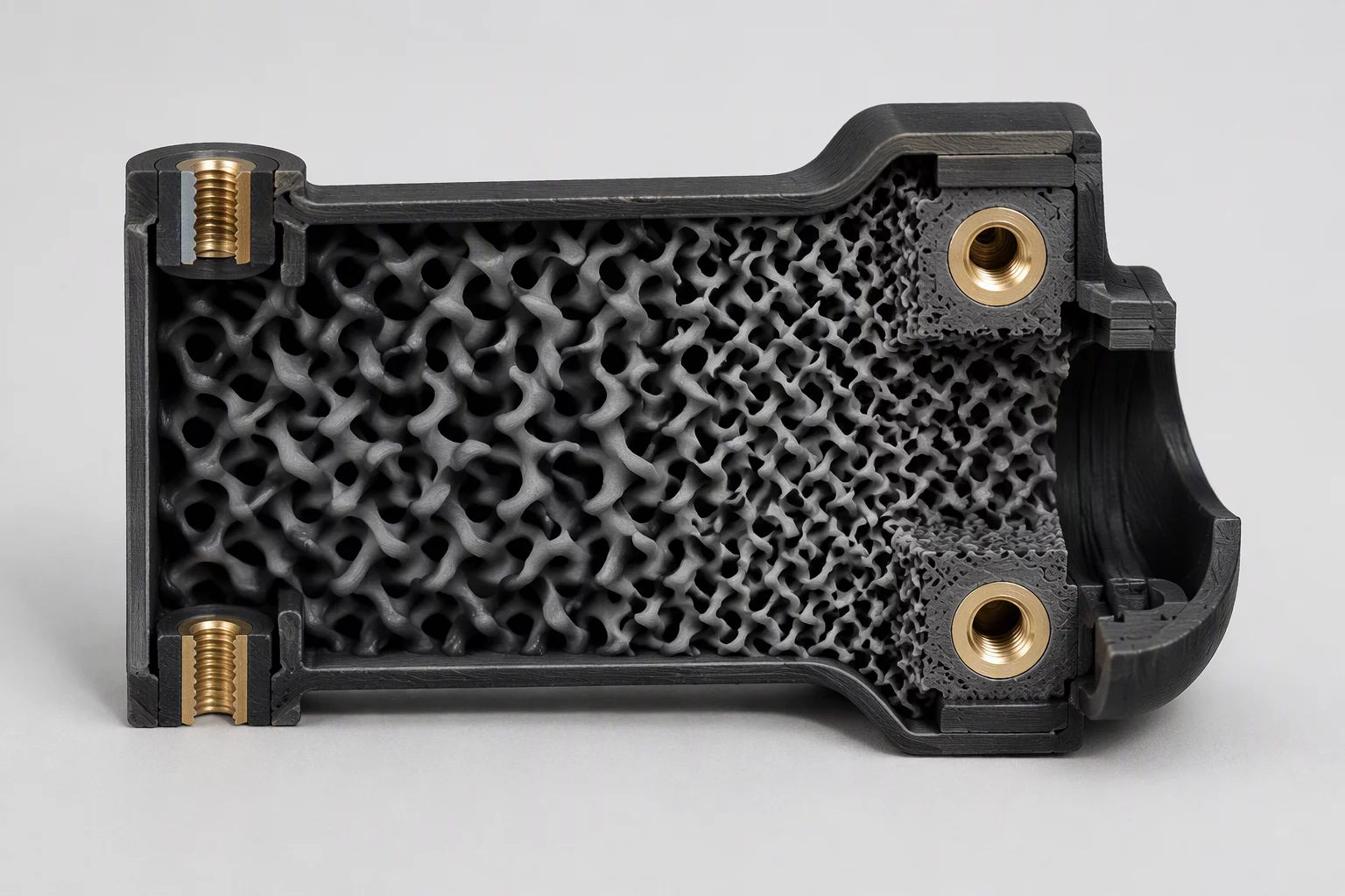
Raising infill globally to satisfy localized stress vectors creates severe inefficiencies across additive manufacturing workflows. Local mesh modifiers decouple regional structural requirements from overall part mass, applying high volumetric density strictly where mechanical hardware seats or shear stresses concentrate.
Operational Realities of Local Modifier Scoping
- Hardware Mounting Integrity: Reinforcing threaded heat-set inserts and counterbores with 60% infill cylinders prevents compressive creep without inflating overall project mass.
- Center-of-Gravity Modulation: Biasing internal density toward lower tiers stabilizes articulated brackets and suppresses top-heavy print wobble during high-speed travel.
- Slicer Hierarchy Precedence: Modifier meshes override parent object infill parameters, recalculating raster density and perimeter loops strictly inside their intersection volume.
- Cycle Time Reduction: Replacing a blanket 45% gyroid regime with a 15% baseline and targeted 55% modifier zones yields 25% to 40% material and runtime savings.
SYSTEMATIC CONTROL OF INTERNAL DENSITY ZONES
Applying modifiers haphazardly introduces boundary artifacts and perimeter collisions. Methodical coordinate placement and volumetric boundary verification ensure clean toolpaths inside modern slicing engines.
Functional prints frequently experience peak stress at fastener pass-throughs, motor flanges, or bearing pockets. Raising infill across the entire CAD model solves fastener pull-out but multiplies filament consumption and expands cycle times unnecessarily.
Scoping a localized cylindrical or box modifier around high-load interfaces allows the slicing engine to elevate density only within critical zones while preserving lightweight structures elsewhere.
- Eliminates internal cooling stresses and warpage caused by excessive solid infill across broad planar geometries.
- Preserves lightweight agility in robotics and drone frames while maintaining reliable torque resistance at mounting points.
- Channels plastic deposition specifically along validated finite-element mechanical stress vectors.
Bambu Studio, OrcaSlicer, and PrusaSlicer provide native primitives such as cubes, cylinders, and spheres for rapid modifier insertion. For complex curved brackets or asymmetric ribbing, native primitives require tedious manual translation that risks misaligning structural boundaries.
Exporting modifier solids alongside parent bodies within a single STEP coordinate system ensures automatic spatial alignment upon import, eliminating guesswork in the slicer 3D viewport.
- Native slicer primitives offer rapid, toolless setup for standard counterbores and rectangular clearance blocks.
- CAD-originated modifier meshes guarantee sub-millimeter compliance along organic contours and non-planar interfaces.
A common failure in multi-part slicing occurs when a secondary volume is imported as an independent sub-part instead of a modifier. The slicer consequently generates complete perimeter shells inside the geometry, creating a distinct boundary seam that separates under mechanical bending.
Designating the volume as a modifier instructs the toolpath generator to omit inner perimeter boundaries, letting dense infill strands tie directly into the surrounding low-density mesh.
- Inspect sliced layer cross-sections to verify no unwanted perimeter loops appear along internal modifier boundaries.
- Calibrate infill overlap percentage to guarantee strong weld connections between differing raster densities.
Tall or cantilevered assemblies printed at accelerations above 10,000 mm/s² suffer from top-heavy harmonic ringing. Placing a modifier block near the base to apply 70% solid infill pulls the center of gravity downward toward the build plate.
Upper sections can then safely run lightweight lightning or adaptive cubic infill, lowering moment of inertia and enabling aggressive kinematics without triggering layer displacement.
- Dampens directional resonance spikes during high-speed gantry reversals on CoreXY and bed-slinger machines.
- Maintains dimensional tolerances on tall vertical walls by stabilizing the base footprint against bed vibration.