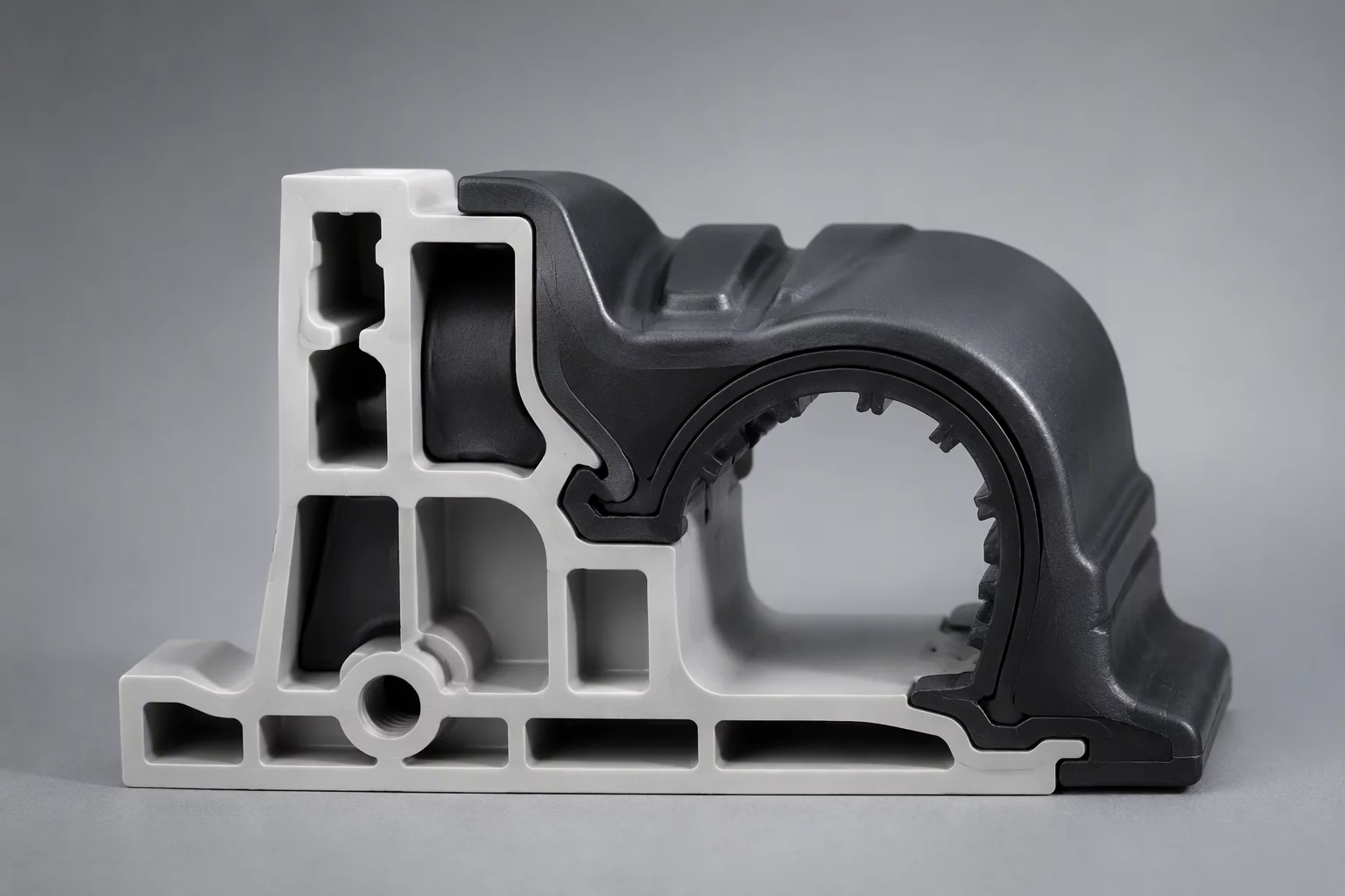
INTERFACE SHELL DELAMINATION MITIGATION
When blending distinct thermoplastic families or co-extruding rigid cores with elastomeric exteriors, interfacial peel strength dictates overall assembly durability. Slicer default perimeter settings frequently generate cold boundary seams or unneeded purge cycles that degrade cycle efficiency.
Operational Interface Principles
- Perimeter Overlap Ratio: Increasing interface perimeter overlap between 25% and 38% provides physical mechanical interlock between polymers with mismatched crystallization temperatures without excessive surface bulges.
- Modifiers Over Global Extrusion: Applying shell layer density adjustments specifically at mating part meshes eliminates redundant prime tower purges on non-contacting vertical Z-layers.
- Thermal Chamber Equilibrium: Matching nozzle purge volumes to thermal gradient requirements prevents crystallization stress cracking along the transition boundary.
- Sequence Order Priority: Printing inner boundary shells before outer decorative walls locks heterogeneous interfaces securely prior to cosmetic perimeter extrusion.
SYSTEMATIC SHELL OPTIMIZATION
Master the four critical configuration steps required to tune multi-material transition shells without destabilizing project-level slicing baselines.
Standard dual-extrusion slicing profiles default to simple abutting vertical surfaces. This configuration creates microscopic planar voids where different polymers contract at contrasting thermal coefficients.
Configuring local modifier volumes along the interface allows targeted perimeter tooth patterns or expanded extrusion width overrides up to 125% of nozzle diameter without altering global model dimensions.
- Set interface shell count to minimum 3 perimeters for sufficient molecular entanglement depth.
- Apply localized infill overlap compensation to ensure dense perimeter-infill anchors at the shear line.
- Restrict custom perimeter widths strictly to modifier intersection zones to preserve exterior dimension tolerance.
Purge tower waste multiplies rapidly when toolhead swaps occur across entire plate heights for cosmetic or boundary shells that only occupy a few vertical millimeters.
Restricting multimaterial assignments strictly to localized child objects within the part hierarchy confines toolhead changes to target layer ranges.
- Isolate multi-material interface layers using Z-range clipping modifiers rather than global extruder maps.
- Leverage infill purge options to absorb color and thermal transitions inside non-critical internal cavities.
Cold interfacial seams emerge when an idling nozzle cools down excessively while the primary extruder deposits internal infill. The freshly deposited interface shell then lands onto solidified plastic without fusing.
Adjusting standby temperatures and part fan delay specifically inside the interface modifier maintains thermal bonding potential across dissimilar resins like PETG and TPU.
- Enforce a 5-second minimum layer time modifier on delicate transition perimeters.
- Disable dynamic part cooling exclusively during the first two boundary perimeter loops.
Prior to sending print jobs to production, preview toolpaths using volumetric speed and extruder color schemes to verify that interface overlaps reflect mechanical intent.
Watch for unanchored perimeter loops or travel stutter at seam start points, which frequently signal incorrect part nesting or modifier boundary clashes.
- Inspect slice preview layer-by-layer to ensure no unintended gap fills occur between boundary shells.
- Validate that retracted toolhead paths do not drag across freshly bonded interface perimeters.