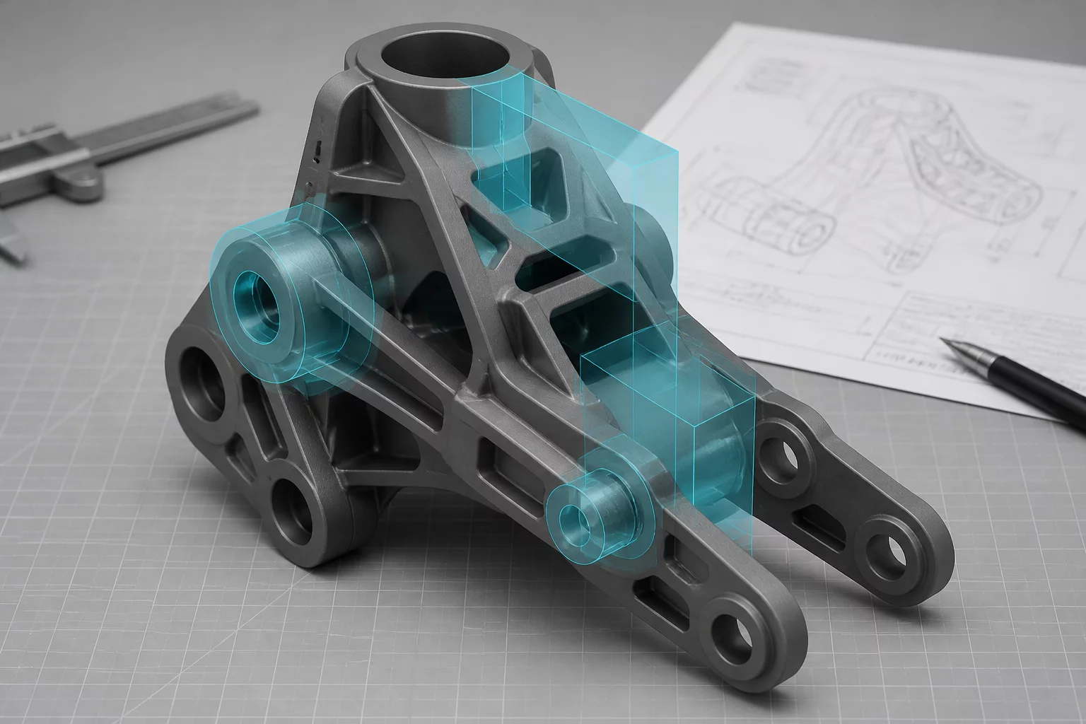
PREPARING MESHES FOR MODIFIER PRECISION
Local slicer modifiers enable selective reinforcement of localized stress zones, custom infill transitions, and targeted shell count changes across complex models. However, poorly structured CAD bodies and non-manifold polygon shells often create slicing calculation conflicts, missing perimeters, or toolpath voids during Boolean slicing operations.
Essential Rules for Modifier Geometry Construction
- Manifold Integrity: Every modifier volume must be an entirely closed 2-manifold solid with outward-facing normals to prevent inversion of toolpath calculations.
- Coplanar Interference: Sharing identical exterior faces between parent components and modifier shells triggers floating-point clipping rounding errors during slicing.
- Origin Synchronization: Exporting child modifiers within the identical global CAD coordinate origin guarantees absolute spatial placement inside the slicing bed.
- Assembly Hierarchy: Multi-body STEP or 3MF containers preserve parent-child relations, allowing modifier reassignment without manual re-indexing.
CAD WORKFLOWS AND BOUNDARY STRATEGIES
Applying geometric modifiers in desktop slicers requires strict CAD export protocols. These four standardized procedures eliminate geometry collisions and ensure predictable toolpath generation.
The most resilient method for passing localized reinforcement geometry into modern slicers is designing them as separate unmerged bodies within the master parametric model. Doing so preserves parametric associativity so that any dimension shift automatically propagates to the modifier volume.
When exported together into a unified STEP or multi-body 3MF file, slicers load the pieces as an assembled unit, maintaining micro-millimeter alignment automatically without manual 3D gizmo adjustments.
- Model the target structural reinforcement as a distinct solid body without executing a final Boolean union.
- Export parent structures and modifier volumes simultaneously into a single STEP AP214/AP242 file.
- Right-click the sub-part within the slicer object hierarchy and convert its role directly from Part to Modifier.
Slicers compute modifiers by performing slice-by-slice 2D Boolean intersections. When the boundary face of a modifier lies exactly on the external wall of the parent component, numerical rounding can cause exterior perimeters to split or leave jagged cosmetic seams.
To preserve clean external walls while altering internal infill density, offset the modifier geometry inward or outward relative to the outer perimeter zone.
- Extend internal structural cores 0.2 mm to 0.5 mm beyond internal void perimeters to guarantee toolpath overlap.
- Recede modifier volumes at least one extrusion line width inside outer cosmetic perimeters when surface finish must remain untouched.
When working with polygonal files like STL or OBJ instead of mathematical boundary representation STEP solids, export resolution plays a critical role. Divergent chordal tolerances between interacting bodies create micro-gaps at slicing layers.
These gaps trigger intermittent solid bridge passes and unintended retractions as the nozzle traverses theoretical voids between non-matching facets.
- Apply uniform angular and chordal deviations across both models during mesh tessellation export routines.
- Delegate mesh discretization directly to the slicer engine by adopting native STEP workflow pipelines.
Support blocker modifiers require different geometric tolerances than infill density overrides. Slicing engines evaluate support interfaces using vertical clearance parameters and bridge overhang angles that extend past theoretical overhang edges.
Designing blocker solids with an intentional buffer envelope ensures that peripheral support structures do not spill into delicate internal threads or horizontal boreholes.
- Envelope critical overhang boundaries with an extra 0.4 mm to 0.8 mm modifier buffer volume.
- Inspect the generated toolpath under volumetric speed and preview line type modes to verify clean boundary demarcation.