Boundary Segregation in Slicing Environments
Modern additive manufacturing software relies on tiered parameter inheritance to reconcile printer-wide kinematic caps with localized part requirements. Clear demarcation ensures expert overrides remain strictly bound to their intended geometric targets without contaminating baseline print profiles.
Foundational Demarcation Tenets
- Inheritance Priority: Parameters cascade top-down from hardware definitions to global process profiles, object-level overrides, and volumetric modifiers.
- Interface Encapsulation: Expert mode toggles govern visible user interface fields but do not alter backend inheritance mechanics or runtime defaults.
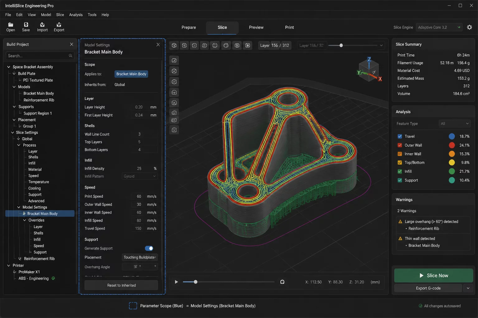
- State Isolation: A parameter modified on an isolated sub-mesh remains encapsulated, preventing silent updates to project-wide printing parameters.
- Audit Traceability: Explicit visual flags highlight deviating settings, allowing manufacturing engineers to distinguish project baselines from temporary patch rules.
Deconstructing Parameter Scope Boundaries
Four operational vectors define how contemporary slicers manage expert parameters, local modifier volumes, and project-level profile consistency.
Contemporary slicer engines organize configuration parameters across three strict structural tiers. Global presets configure universal variables such as kinematic limits, bed temperature, retraction speed, and volumetric flow ceilings that apply to the entire machine envelope.
When an individual piece within a production plate demands altered shell thickness or perimeter velocity, an object-level exception supersedes the global baseline without altering the underlying configuration file on disk.
- Global tier locks hardware kinematics, universal thermal states, and default material extrusion factors.
- Object tier introduces localized modifications such as wall count, fill pattern, and seam coordinate alignments.
- Sub-mesh modifier tier applies localized density or perimeter changes strictly bounded within an intersecting geometric volume.
Switching between Basic, Advanced, and Expert interface modes frequently misleads operators into believing that parameter behavior has changed. These visibility switches serve entirely as view filters to protect novice operators from complex configuration options.
Any parameter modified while in Expert visibility remains active and influential within the internal slicing engine, even when an operator subsequently reverts the interface to Basic mode.
- Interface view modes alter visual control density while preserving identical compilation logic.
- Hidden expert overrides continue to dictate G-code extrusion coordinates during toolpath calculation.
Accidental contamination occurs when an operator attempts to rectify a part-specific imperfection by adjusting global baseline presets instead of creating a localized modifier. The resulting profile shift degrades neighboring objects that were previously printing within tolerance.
Modern slicers mitigate this hazard by highlighting non-default fields with visual reset glyphs and color markers, enabling operators to audit where exceptions have been introduced.
- Global profile alterations must be restricted to changes that demonstrably benefit every model on the build surface.
- Audit glyphs provide real-time visual feedback indicating whether an override originates at the project, object, or modifier tier.
When saving project archives across engineering teams, clear demarcation between external master profiles and local project bundles preserves reproducibility. Master profile updates should never silently overwrite verified project-specific exceptions.
Implementing disciplined parameter auditing ensures that when a 3MF container is opened months later, the exact balance of baseline presets and local overrides remains intact without unintended profile inheritance.
- Store project-specific modifiers directly within the container archive rather than modifying shared centralized profiles.
- Validate parameter inheritance trees prior to releasing production G-code packages to the manufacturing floor.