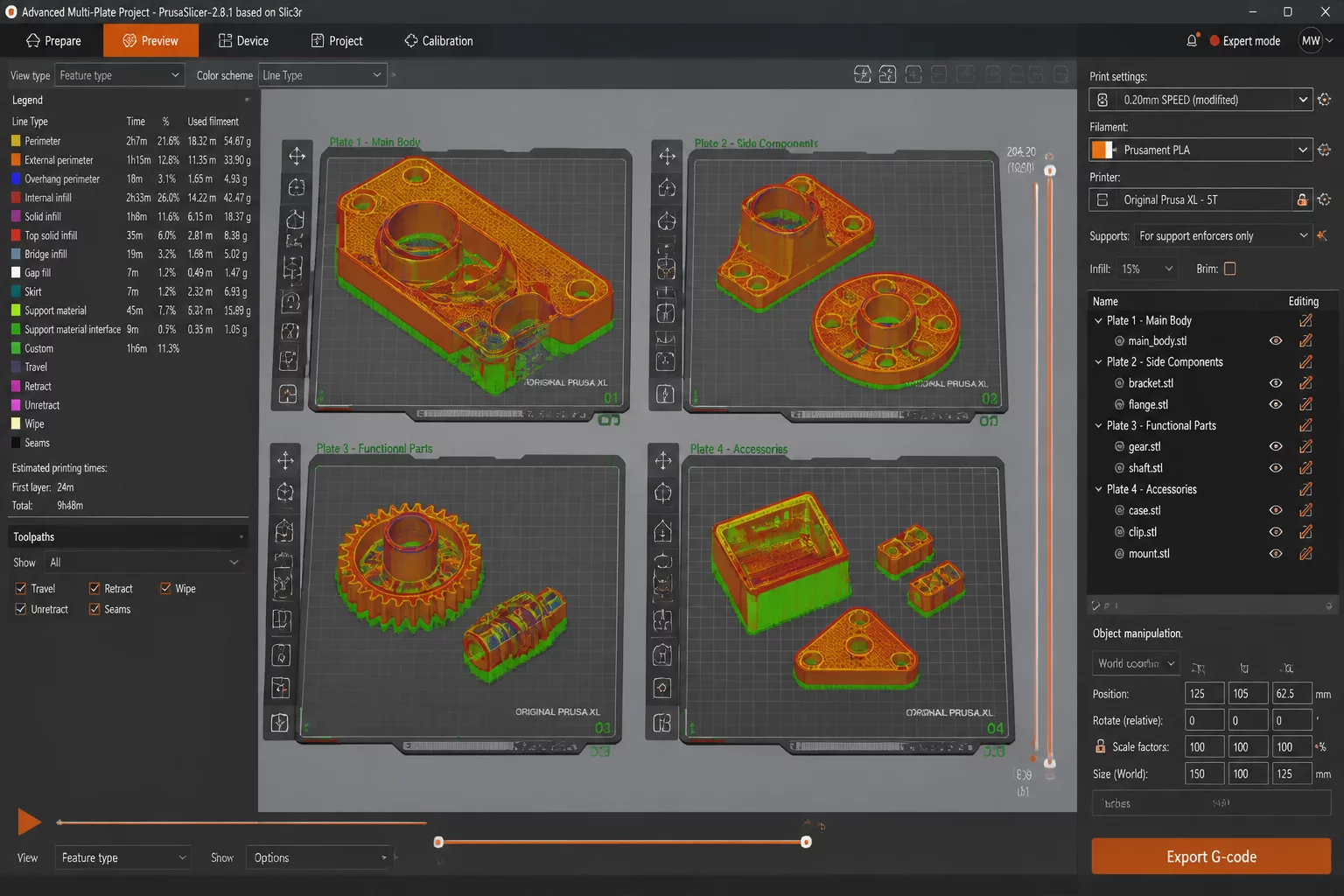
ARCHITECTURAL MULTI-PLATE INTEGRATION
Managing complex multi-part mechanical enclosures previously demanded scattering files across separate project saves or clustering mismatched parts onto a crowded single plater. The multi-plate framework introduces clean boundaries between individual build beds while keeping the entire bill of materials unified in one source file.
Core Engineering Takeaways
- Workspace Structure: Consolidates all assembly sub-components inside a single 3MF project container while preserving individual bed coordinates and part orientations.
- Plate-Level Overrides: Enables discrete bed temperatures, distinct build surface sheet selections, and individual brim configurations per canvas without parameter bleeding.
- Sequential Safety: Dynamically calculates printhead clearance envelopes on sequential plates while allowing conventional batch layer printing on adjacent plates.
- Targeted Dispatch: Generates clean standalone G-code binaries per plate or streams targeted print jobs directly to selected farm units across PrusaConnect.
STEP-BY-STEP MULTI-PLATE PRACTICUM
Follow this four-stage execution routine to stage structural components, isolate thermal and mechanical parameters, verify toolpath envelopes, and dispatch jobs cleanly.
Organizing a functional multi-part assembly begins with parsing mechanical components based on stress criteria, required orientation, and material compatibility rather than dropping all STLs haphazardly onto a single build plate.
The preview release workspace introduces plate tabs along the top viewport border. Adding consecutive plates establishes independent build envelopes while maintaining project-wide visibility in the left-hand object hierarchy.
- Import complete mechanical assemblies directly into Plate 1 to maintain relative CAD alignment coordinates.
- Right-click structural load-bearing housings in the object tree and designate them to Plate 2 for thicker shell profiles.
- Retain delicate interface clips and threaded fasteners on Plate 1 for micro-layer precision tuning.
Sequential printing significantly improves dimensional precision by eliminating travel crossing paths across parts, yet previous implementations forced an entire project into sequential restrictions.
The multi-plate paradigm allows Plate 2 to operate in Complete Individual Objects mode while Plate 1 and Plate 3 execute standard synchronous layer passes without triggering validation conflicts.
- Define printer extruder clearance radius and gantry height in machine limits before enabling sequential passes.
- Arrange parts across Plate 2 following front-to-back coordinate order to guarantee unobstructed toolhead travel.
Additive production projects frequently combine dissimilar materials, pairing stiff carbon-reinforced composites for internal skeletons with ductile co-polyesters or tough PETG for outer protective shells.
Each plate now associates with its own print sheet texture profile, first-layer bed thermal targets, and preheat dwell timings without writing conflicting overrides to the global filament preset.
- Designate powder-coated textured sheets for composite nylon on Plate 2 to preserve bottom release characteristics.
- Set smooth PEI adhesion profiles at 60 degrees Celsius for PLA cosmetic trim pieces located on Plate 1.
Before sending commands to production hardware, verifying individual toolpath trajectories ensures modifier meshes on one plate have not leaked into geometry on neighboring plates.
The updated G-code inspection preview displays individual layer time distributions, volumetric extrusion velocities, and cooling fan duty cycles isolated plate by plate.
- Inspect volumetric speed legends per plate to confirm high-flow perimeter modifiers remain strictly local.
- Export discrete .gcode files directly or push ready jobs directly to individual print farm workers via PrusaConnect.